NEWS
12
Aug

Ceramic CBN Grinding Wheels:Root Causes and Solutions for Camshaft Corner Chipping

Share:

Introduction


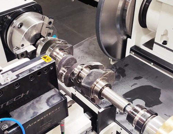
Camshaft grinding is one of the most demanding operations in automotive powertrain manufacturing. The lobes, journals, and corner radii of a camshaft must meet micron-level tolerances while enduring the extreme mechanical and thermal loads of high-volume production. Ceramic bonded CBN (cubic boron nitride) grinding wheels have become the industry standard for this task because of their exceptional hardness, thermal stability, and long service life. Yet even with premium CBN wheels, manufacturers frequently encounter a frustrating defect: corner chipping on camshaft lobes after an initial period of stable machining.
This article examines the root causes of corner chipping during long-term CBN camshaft grinding and provides actionable solutions — from wheel selection and CNC program optimization to workholding inspection and coolant management. The insights draw on decades of field experience from More Superhard, a leading Chinese manufacturer and exporter of superhard grinding solutions serving automotive plants across Asia, Europe, and the Americas.

1. Why Corner Chipping Appears After Stable Grinding


During the initial stage of a grinding cycle, a freshly dressed CBN wheel cuts cleanly and produces the required surface finish. After processing hundreds or thousands of parts, however, the process can suddenly produce corner chipping. Understanding why this happens requires looking at multiple interacting factors.

                                  Root Causes and Solutions for Camshaft Corner Chipping

1.1 Grinding Wheel Wear, Dulling, and Profile Deformation


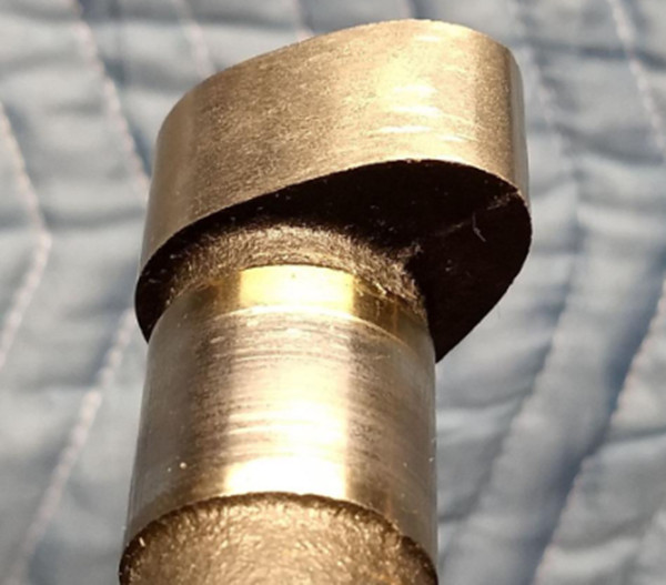
A newly dressed CBN wheel has sharp cutting edges with excellent cutting performance. As production continues, the abrasive grains gradually wear and the bond retains worn grains longer than ideal. The grinding process shifts from efficient cutting to plowing and friction, which increases grinding force substantially. The sharp corners of the camshaft lobe then experience excessive localized stress, leading to micro-cracks that propagate into visible chipping.
Additionally, when the wheel profile loses its intended geometry — roundness or form accuracy — vibration can develop during the grind. The resulting impact forces directly damage the workpiece's sharp edges. Operators should watch for these telltale signs:
  • Grinding force gradually increases over successive parts
  • Surface roughness deteriorates beyond specification
  • Burn marks appear on the workpiece surface
  • Corner chipping emerges after a predictable number of parts

1.2 Grinding Parameters and CNC Program Issues


                    Root Causes and Solutions for Camshaft Corner Chipping

Incorrect grinding parameters or poorly optimized CNC programs can generate excessive impact forces at the point of wheel-workpiece engagement. Common problems include:
  • Excessive depth of cut per pass, overloading the CBN grains
  • Feed rates that are too aggressive for the wheel's self-sharpening capability
  • Sudden engagement between the grinding wheel and workpiece without ramp-in
  • No approach or retract clearance, causing the wheel to dwell at corner features
  • Missing radius transitions at camshaft steps or sharp profile corners
When the grinding wheel impacts a camshaft corner without a smooth transition path, local stress concentration spikes dramatically, causing edge fracture even on a wheel that is otherwise performing well.

1.3 Long-Term Vibration and Workholding Looseness


At the start of a production run, the workholding system is stable and well-adjusted. Over weeks or months of continuous grinding, however, cumulative wear introduces subtle changes:
  • Center points lose contact pressure and develop micro-play
  • Steady rests shift from their original calibrated position
  • Clamping force decreases as fixture components wear
  • The workpiece develops small radial or axial movements during grinding
Even a few microns of unexpected workpiece movement can cause the grinding wheel edge to impact the camshaft corner at an unfavorable angle, initiating chipping that worsens with each subsequent part.

1.4 Thermal Damage and Surface Embrittlement


Insufficient cooling during continuous high-volume grinding allows heat to accumulate in the grinding zone. Elevated temperatures can alter surface hardness, generate residual thermal stresses, and cause localized embrittlement of the workpiece surface. A hardened and brittle surface layer becomes hypersensitive to mechanical impact — even a modest grinding force can trigger corner cracking or chipping under these conditions.
Effective countermeasures include:
  • Increasing coolant flow rate and pressure to flood the grinding contact zone
  • Ensuring coolant nozzles are positioned to deliver fluid directly into the wheel-workpiece interface
  • Regularly inspecting and cleaning nozzle orifices to prevent blockage from swarf buildup

1.5 Hidden Defects in Raw Material


Some camshaft blanks contain defects that are not visible before grinding begins: small subsurface cracks, casting or forging porosity, sharp burrs from prior machining, or residual stress concentration zones. During rough grinding these defects may remain hidden beneath the machining allowance. Once the surface layer is removed, the defects become exposed and can cause sudden, unpredictable corner chipping that is unrelated to wheel condition or process parameters.

2. Emergency Response: What to Do When Chipping Occurs

2.1 Sudden Chipping During Production


When corner chipping appears unexpectedly on the production line, follow this three-step protocol:
Step 1 — Immediate Wheel Dressing: Perform a complete dressing cycle using a diamond roller or rotary dressing tool. The goal is to restore the wheel's profile geometry, remove loaded swarf, and expose fresh CBN cutting edges. If necessary, perform an additional sharpening pass to improve the wheel's self-sharpening characteristics.
Step 2 — Reduce Grinding Load: Decrease the depth of cut, reduce the feed rate, and increase coolant supply. This combination lowers the grinding force and prevents further damage while production resumes.
Step 3 — Inspect Workholding: Re-check center point pressure, steady rest alignment, and fixture rigidity. Re-tighten or replace worn components to eliminate vibration caused by workpiece micro-movement.

2.2 Repairing Finished Parts with Corner Damage


The appropriate repair strategy depends on the severity of the damage:
  • Small chipping: Use a fine oil stone for manual edge rounding, remove sharp edges, and verify that all dimensional and surface finish requirements are still met. If quality criteria are satisfied, the part may continue in service.
  • Medium chipping: If sufficient machining allowance remains, return the part to the grinding machine for light re-grinding with a smooth transition at the damaged corner. Avoid aggressive stock removal to prevent further cracking.
  • Severe chipping: Large or deep fractures may compromise the camshaft's structural integrity and dimensional accuracy. Such parts should be scrapped rather than repaired.

3. Long-Term Preventive Strategies


3.1 Optimize CBN Grinding Wheel Selection

Choosing the right ceramic bonded CBN wheel is the foundation of chipping-free production. A wheel that is too hard will dull during long production runs and increase grinding force, while a wheel that is too soft will wear prematurely and require excessive dressing. More Superhard works with each customer to develop a custom bond formulation that balances hardness, self-sharpening behavior, and profile-holding capability for the specific camshaft material and production volume.
Key selection parameters include:
  • Bond hardness grade — tuned to the workpiece material and cycle time
  • CBN grain concentration and size — optimized for surface finish and stock removal rate
  • Dressing interval — calibrated to maintain cutting performance without excessive wheel consumption

3.2 Optimize CNC Grinding Programs


Modern CNC grinding programs should incorporate:
  • Safety clearance between approach and engagement positions
  • Smooth ramp-in and ramp-out movements to eliminate sudden wheel-workpiece impact
  • Radius transitions at all camshaft corners and step features
  • Adaptive infeed strategies that reduce depth of cut as the wheel wears

3.3 Improve Workpiece Preparation


Before camshafts enter the grinding cell, they should be inspected and pre-treated to minimize the risk of chipping. Effective preparation includes deburring all sharp edges, pre-rounding corner features to a minimum radius, and inspecting raw material for casting defects using non-destructive testing methods such as magnetic particle inspection or ultrasonic scanning.

3.4 Establish a Process Monitoring System


A structured monitoring program catches degradation before it produces defects:
  • Track grinding wheel condition and enforce dressing schedules based on part count or force threshold
  • Monitor coolant pressure, flow rate, and nozzle condition at every shift change
  • Inspect fixture clamping force and center point condition at defined intervals
  • Use in-process gauging or acoustic emission sensors to detect the onset of vibration or chatter

Conclusion


Camshaft corner chipping after a period of stable CBN grinding is rarely caused by a single factor. It is typically the combined result of grinding wheel wear, excessive grinding force, workholding vibration, thermal damage, and latent material defects. The most effective long-term solution is to optimize the complete grinding system — wheel selection, dressing management, machining parameters, coolant delivery, workholding stability, and incoming material quality — as an integrated whole.
More Superhard has supported automotive grinding operations worldwide with custom-engineered ceramic bonded CBN wheels, technical consulting, and on-site process optimization. Whether you are setting up a new camshaft grinding line or troubleshooting chronic chipping on an existing line, our engineering team can help you achieve stable production quality and extend grinding wheel life. Contact us at www.moresuperhard.com to discuss your application.
FOLLOW US
This Blog keeps our valued customers informed of important Radiac News and Events, and in the industries we serve.
Copyright © 2003-2023 More SuperHard Products Co., Ltd
Home
Whatsapp
E-mail
Inquiry